Microcontroller Based Projects LIST for ECE students

Microcontroller Based Projects LIST

Multi Task Industrial Timer Using Microcontroller* Multi Task Industrial Timer Using Microcontroller
* Digital Clock Using AT89C2051 Microcontroller
* Laser Based Automatic Visitor Counter cum Room Light Controller
* Biomedical Data Transmission Using Wireless Network
* Digital Clock Using AT89C51 Microcontroller
* Industrial Automation using computer’s parallel port (Visual Basic)
* Digital Day And Date Display Using Microcontroller
* Digital Countdown Timer Using Microcontroller
* Digital 74 Series IC Tester
* Digital Visitor Counter Using Microcontroller
* DS1620 Based Temperature Controller Using Microcontroller
* DS1820 Based High Precision Temperature Indicator Using Microcontroller
* Electronic Voting Machine Using Microcontroller
* Electronics Components Tester Using Microcontroller
* Biometric Security System (Finger Print Based)
* Ultrasonic Distance Meter using microcontroller
* Mobile Controlled Robot Machine
* Telephone Controlled Device Switching Using Microcontroller
* Infrared Interrupt counters Using Microcontroller
* 6 Line and one fan Infrared Remote Switch Using Microcontroller
* Infrared Remote Switch Using Microcontroller
* Interactive Voice Response System (IVRS)
* Line Following Robot Using Microcontroller
* Microcontroller Based Telephone Caller ID
* Microcontroller Based Digital Clock with Alarm
* Password Based Digital code Lock Using Microcontroller
* Multi function Running Lights Using Microcontroller
* Parallel Telephone instrument with secured privacy Using Microcontroller
* Computer to microcontroller communication (Wireless) Using Microcontroller
* PC BASED DATA LOGGER Using Microcontroller and Visual Basic
* Computer Based Digital IC Tester
* GPS
* PC Controlled Robot Machine
* Control Ur PC by remote Control
* Simcard Based Prepaid Energy Meter Using Microcontroller
* Industrial Automation and message transmission using internet
* Digital Clock with Remote controlled time settings Using Microcontroller
* Electric Energy Meter Reading Through Wireless
* Wireless Controlled Robot Machine
* RFID Based Attendance System
* RFID Based Security System
* Data Transmission Through wireless network
* Sending SMS To Landline Telephone Using Microcontroller
* Wireless Data Communication (AT89S52)
* Efficient Solar Energy generation using movable solar panel
* Motor controller using Telephone
* Industrial control using Telephone
* Temperature controlled Colling Fan Using Microcontroller
* Time Operated Electrical Appliances Controlling System
* Traffic signal Controller Using Microcontroller
* Two Line Intercom Using Microcontroller
* Microcontroller-based LED Light Chaser
* Microcontroller-based Temperature Indicator
* PC-based Wireless Stepper Motor Control
* Microcontroller-based Ring Tone Player
* Solar LED Lighting System
* Clap-operated Appliance Control
* Microcontroller-based Speedometer-Cum-Odometer
* PC-Based Mobile Robot for Navigation
* Solar Electric Fence
* Four-Channel Analogue-to-Digital Converter
* Microcontroller-based Temperature Meter
* Kapalbhati Pranayama Timer
* Microcontroller-Based Inductance Meter
* Cellphone-Operated Land Rover
* Presentable Timer Using Secret-Coded Punched Card
* Rank Display System for Race and Quiz Competitions
* Remote-Controlled Toy Boat
* Microcontroller-Based Heart-Rate Meter
* Multiple Devices Switching Through Parallel Port
* Microcontroller-Based Capacitance Meter
* Token Number Display
* Microcontroller-Based DC Motor Speed Controller
* MICROCONTROLLER-BASED TEMPERATURE INDICATOR
* Buzzer Controller for 8-Team Quiz Contests
* Microcontroller-based Ultrasonic Distance Meter
* Microcontroller-based Tachometer
* Temperature Indicator-cum-Controller
* Microcontroller-Based Alarm Clock
* Simple PC-Based Digital Sound-Level Meter
* Low-Cost Versatile Timer Using AT89C2051
* Parallel-Port Interfacing and Programming Aid
* Digital Heart-Beat Counter
* Secured Room Access System
* Digital Voltmeter
* Microcontroller-based Graphics Display
* Microcontroller-based Industrial Timer
* Standalone Digital Clock
* PC-based Dual DC Motor Controller
* Wireless Messaging Via Mobile/Landline Phone
* Microcontroller-based Infrared Tracking Robot
* Remote-Controlled Real-Time Clock with Device Controller
* Auto Controller for Petrol-Run Power Generator
* Design Your Own Infrared Remote
* PIC16F84-based Digital Thermometer
* Water-level Controller-cum-motor Protector
* Digital Phase Selector
* Microcontroller-based Bidirectional Visitor Counter
* Microcontroller-based Automatic Flush System
* Two-Channel PC-based Oscilloscope
* Quiz Buzzer
* Stepper Motor Controller Using AT89C51
* Beverage Vending Machine Controller
* Digital Thermometer-cum-Controller
* Digital Weight Accumulator
* Remotely Programmable RTC-Interfaced Microcontroller for Multiple Device Control
* Auto Switch for TV
* Microcontroller-based Code Lock
* Microcontroller-based Triggering Circuit for SCR Phase Control
* Parallel-Port Testing and Programming Aid
* Fastest-Finger-First Using Microcontroller
* Remote-Controlled Land Rover—A DIY Robotic Project
* 3D Surround Sound System
* AVR Microcontroller-Based Clock
* Automatic Rain Timer
* Power Factor Correction
* AT89C2051-Based Countdown Timer
* PC-Based Remote-Controlled Stepper Motor
* Low-Cost LCD Frequency Meter
* PC-Based Transistor-Lead Identifier
* A Simple Directional Detector/Counter
* Using AVR Microcontroller for Projects—Part 3 of 3
* Speed Checker for Highways (2005)
* Using AVR Microcontroller for Projects—Part 2 of 3
* Automatic 3-Phase Induction Motor Starter
* Using AVR Microcontrollers for Projects—Part 1 of 3
* Noise-Muting FM Receiver
* Digital Stopwatch
* Remote-Controlled Stepper Motor
* Computerized Electrical Equipment Control
* Manual AT89C51 Programmer
* Medium-Power Low-Cost Inverter
* Programmable Timer Based on AT90S4433 AVR
* Low-Cost Energy Meter Using ADE7757
* Two-Wheeler Security System
* Auto Changeover to Generator on Mains Failure—Part II
* PC-based Scrolling Message Display
* Auto Changeover to Generator on Mains Failure—Part I
* Device Control through PC’s Parallel Port Using Visual Basic
* Remote-Controlled Digital Audio Processor
* Microcontroller-based Real-time Clock
* Standalone Scrolling Display Using AT90S8515 AVR
* Moving Message Over Dot-Matrix Display(2004)
* Ultrasonic Lamp-Brightness Controller
* Digital Combination Lock
* Safety Guard for the Blind
* Microprocessor-Based Home Security System
* Stepper Motor Control Using 89C51 Microcontroller
* Dynamic Temperature Indicator and Controller
* Voice Recording and Playback Using APR9600 Chip
* Load Protector with Remote Switching Facility
* PIC16F84-Based Coded Device Switching System
* Remote-Controlled Sophisticated Electronic Code Lock
* Temperature Indicator Using AT89C52
* Device Switching Using Password
* Laser-Based Communication Link
* Programmer for 89C51/89C52/89C2051 Microcontrollers
* A Bidirectional Visitors Counter
* Digital Clock Using Discrete ICs
* Lift Overload Prevented
* Sound-Operated On/Off Switch
* Digital Water-Level Indicator Cum Pump Controller
* PC-Based Data Logger
* Automatic Water-Level Controller
* Microcontroller-Based Call Indicator
* Controlling a 7-Segment Display Using PC’s Parallel Port(2003)
* Economical UPS for Cordless Phones
* Binary-To-Hexadecimal Decoder
* Proportional Load Control Using PC
* Multifactor Emergency Light
* Fluid Level with Indicator
* Microcontroller-Based School Timer
* Telephone Remote Control
* Auto-Control for 3-Phase Motors
* Programmable Melody Generator -Part II

electrical engineering students project Automatic Railway Gate Control & Track Switching

Automatic Railway Gate Control & Track Switching

This project utilizes two powerful IR transmitters and two receivers; one pair of transmitter and receiver is fixed at up side (from where the train comes) at a level higher than a human being in exact alignment and similarly the other pair is fixed at down side of the train direction. Sensor activation time is so adjusted by calculating the time taken at a certain speed to cross at least one compartment of standard minimum size of the Indian railway. We have considered 5 seconds for this project. Sensors are fixed at 1km on both sides of the gate. We call the sensor along the train direction as ‘foreside sensor’ and the other as ‘aft side sensor’. When foreside receiver gets activated, the gate motor is turned on in one direction and the gate is closed and stays closed until the train crosses the gate and reaches aft side sensors. When aft side receiver gets activated motor turns in opposite direction and gate opens and motor stops. Buzzer will immediately sound at the fore side receiver activation and gate will close after 5 seconds, so giving time to drivers to clear gate area in order to avoid trapping between the gates and stop sound after the train has crossed.

The same principle is applied for track switching. Considering a situation wherein an express train and a local train are traveling in opposite directions on the same track; the express train is allowed to travel on the same track and the local train has to switch on to the other track. Two sensors are placed at the either sides of the junction where the track switches. If there’s a train approaching from the other side, then another sensor placed along that direction gets activated and will send an interrupt to the controller. The interrupt service routine switches the track. Indicator lights have been provided to avoid collisions. Here the switching operation is performed using a stepper motor. Assuming that within a certain delay, the train has passed the track is switched back to its original position, allowing the first train to pass without any interruption. This concept of track switching can be applied at 1km distance from the stations.

final year engineering students : Controller Area Network based projects

Controller Area Network based projects

  Car head light system.

  Car door locking system.

  Car window adjustment system.

  Car mirror adjustment system.

  Car a.c control system using temperature.

  Car engine temperature display.

  Car upper layer temperature display system.

  Car seat adjustment system.

  Home appliances controlling system using can protocol.

  Volvo bus engine temperature display system.

  Can protocol based data acquisition system.

  Can networking for cars (controller area network of Bosch)

  Can protocol based automotive street light switching system.

  Temperature based d.c motor speed control using can protocol.

  Can protocol based traffic light system.

  Real time security system using can protocol.

  Robot controlling using can protocol.

  PC based data acquisition system using can protocol.

GPS based projects for computer science engineering

GPS based projects

Vehicle tracking system with GPS & GSM.

Interfacing GPS receiver with microcontroller

   GPS & GSM based car security system. Easy to find the stolen car.

   Standalone GPS coordinates (latitude, longitude) locater.

  GSM+GPS based school kids tracking system

  Grasping latitude and longitude position interfacing using global position system.(GPS).

  GPS based base monitoring

 GPS based highway vehicle monitoring system

Final Year Engineering project topics for CSE students

Final Year Engineering project topics

GPS based projects

1. Vehicle tracking system with GPS & GSM.--
2. Interfacing GPS receiver with microcontroller.—
3. GPS & GSM based car security system. Easy to find the stolen car.--
4. Standalone GPS coordinates (latitude, longitude) locater.—
5. GSM+GPS based school kids tracking system.—
6. Grasping latitude and longitude position interfacing using global position system.(GPS).
7. GPS based base monitoring.—
8. GPS based highway vehicle monitoring system.--

Embedded based projects

1. Can protocol implementation to enable robust serial communication for automotive applications.
2. Manchester code decoding controls the robot direction by TV remote.—
3. Intelligent machine design by accessing the wireless commands.—
4. Access control system using i-button with secret lock system.—
5. Electronic eye with security system using RF with message broadcasting—
6. Wireless digital energy meter.—
7. Can networking for cars (controller area network of Bosch).--
8. Design a prepaid electricity billing system using microcontroller.--
9. Microcontroller based fire monitoring system in petrochemical industries--
10. Interfacing color sensor with different wave lengths to microcontroller.—
11. Electronic door code lock using microcontroller.—
12. 8-channel data logger.—
13. Temperature monitoring and control.—
14. Bank token display system –
15. Stepper motor control using microcontroller.--
16. Traffic light system.—
17. Modern house automation (ac/dc) using RF communication.--
18. Modern home (ac/dc) automation using GSM module.—
19. RFID based home/office security system.—
20. Tracing down the vehicle using GSM &satellite communication system
21. Automatic street power saving system with light dependent resistor.—
22. Temperature dependent dc fan speed control using thermistor---
23. Password operated industrial machinery control (wireless, more than 8 machineries).—
24. Digital lock.—
25. Electronic voting machine—
26. Industrial protection system using temperature, smoke sensors and light dependent resistor.3200/-
27. Stepper motor controller.—
28. Wireless chatting using RF.—
29. Interfacing a graphical LCD to microontroller.
30. Designing a prepaid electricity billing system using microcontroller for electric meter reading.
31. Wireless ac/dc device control for appliances using remote control.--
32. Self powered solar data logger.—
33. Microcontroller based fire monitoring system in petrochemical industries.—
34. Detecting the conditions of remote areas through data acquisition system using RF module.
35. Embedded based electronic code locking system.—
36. Microcontroller digital access control system—
37. Season based automatic streetlights switching.---
38. Microcontroller based temperature monitoring & contro—
39. Code request for door opening system.--
40. Autonomous robot that recognizes the obstacles and changes the path by it self using infra-red.—
41. Compact zigbee hand held unit for robot control.—
42. Real-time industrial process monitoring & control using GSM phone.—
43. High performance zigbee protocol implementation for RF communication.—
44. Microcontroller based unmanned bi-directional load carrier—
45. Embedded based digital object counter.—
46. Access control system using i-button.(1-wIRe protocol)—
47. Microwave heat oven temperature display system.—
48. Access control system with automatic door opening system. –
49. Password based electrical appliances control system using 89c51.—
50. RTC based intelligent automatic street light control using 89c51.—
51. 8-channel industrial security system using 89c51 MCU.—
52. Speed control of dc motor using pulse-width modulation.—
53. Graphical lcd display.—
54. Electronic eye 8051 based.—
55. Industrial automation & monitoring system.—
56. Detecting the conditions of remote areas through data acquisition system using RF module.
57. RFID based office attendance logger.—
58. RFID based parcel tracing system.—
59. Autonomous robot with path tracer.--
60. Implementation of colour sensor using 89c2051 microcontroller.—
61. Development of an embedded system for graphic information display.--
62. Development of an embedded system for multiprotocol data communication—
63. Zigbee stack development for industrial automation.--
64. Zigbee stack development for computer networking.—
65. Zigbee stack development for home automation.--
66. Design & implementation of RF based security system for industries
67. Wireless based (RF) industrial automation system.—
68. Implementing process control & monitoring system using can.—
69. Design and implementation of home automation using can.--
70. Implementing wireless PC to PC communication using RF.--
71. Automatic railway gate system.—
72. Microcontroller based standalone temperature measurement system.—
73. Fire fighting robotics with artificial intelligence.—
74. Embedded password based security door lock system using 89s52.—
75. LDR based power saver for street light control system using 89s52.—
76. Implementation of colour sensor.—
77. Energy meter with prepaid card.—
78. Automatic shopping mall door opening.—
79. Range measurement using IR.—
80. Microcontroller based reversible d.c motor control.—
81. Multilevel car parking by MCU
82. Automatic railway crossing Gate controller.—
83. Electronic eye with security system.---
84. Microcontroller based scrolling message display---
85. Light sensing robot.—
86. Voltage logger.—
87. Temperature control and monitoring.---
88. Wireless data acquisition. --
89. SPDT relay with under/over voltage protection. --
90. Programmable digital timer cum clock. --
91. I2C Based Weather Station Recorder. --
92. Metal Detector using microcontroller. --
93. Single channel data acquisition system (PC interface). –
94. Dual channel data acquisition system (PC interface).—
95. Multi-channel data acquisition system (PC interface).—
96. Eight channel data acquisition system (PC interface).
97. Data acquisition system with control system (PC interface). –
98. Intruder and burglar alarm—
99. Fire sensing and control system. –
100. Multi-channel fire sensing and control system

Final Year engineering projects ECE

Final Year engineering projects

IR based projects
1. Intelligent machine design by accessing the wireless commands.
2. Manchester code decoding controls the robot direction by Philips TV remoteTarget catching robotic arm manipulator (using IR communication
3. Wireless data communication through IR led and IR detector
4. Modern house automation (ac/dc) using IR communication.—
5. Pick and place robot.—
6. Autonomous robot with path tracer.—
7. Anti-theft alarm system.—
8. Automatic room light controller with visitor counter (IR sensor).—
9. Intelligent object counting system.—
10. Autonomous robot.—
11. Rc5 IR based remote device switching (IR remote).—
12. Channel IR based remote control.—
13. Home automation (ac/dc) using TV remote.—
14. Wireless vehicle path tracer using IR&RF.—
15. Robot arm manipulator.—
16. Blind stick robot.—
17. Automatic railway gate system.—
18. Token number display using IR.—
19. IR based distance measurement system.—

PC based projects
1. Home automation (ac/dc) using PC interface.—
2. PC based data acquisition system using (max232).—
3. Microcontroller enabled PC based industrial protection.—
4. Robot direction controlling using RF communication .remote monitoring any alarm on PC using radio communication.—
5. Miniature real-time controller (6-channel outputs) with PC interface and i2c protocol.—
6. GPS navigator/logger (microcontroller board +PC software)—
7. PC based dc motor speed control—
8. RF based communication system between keypad and PC—
9. 8 channel remote control using PC—
10. PC based smart home ---
11. PC based street light controller –
12. PC based temperature monitoring and control—
13. PC based remote controlled wireless automation system—
14. PC based ADC interfacing –
15. Industrial automation via PC .--
16. PC based data acquisition system by stimulating SPI and I2C protocol implementation.-
17. Microcontroller Based GSM and Pc interface.--
18. PC based robot controlling.—
19. Robotic arm manipulator using PC.
20. RFID data logger using PC.—

RF communication projects

1. Modern house automation (ac/dc) using RF communication.—
2. Electronic eye with security system using RF with message broad casting.--
3. Advanced rail way signaling process by excluding manpower using RF.—
4. Incoming/outgoing vehicle alert from main gate. To control office using SMS transmitting through RF module.—
5. Robot direction controlling using RF module.--
6. SMS transmitting using RF modules.—
7. Wireless data acquisition system using RF.—
8. Industrial automation system using RF.—
9. Wireless data encryption and decryption using RF communication.—
10. Hi-tech wireless equipment controlling system.—
11. Home / office security system (safeguard) using RF.--
12. Railway gate control system using RF.—
13. Detecting the conditions of remote areas through data acquisition system using RF module.
14. Microcontroller based fire monitoring system in petrochemical industries using   RF communication—
15. Channel RF based remote control.—
16. Wireless digital code lock with a status display.—
17. Electrical apparatus control system in a plant using RF wireless communication.—
18. RF based remote controlled wireless automation system –
19. RF access system .—
20. RF Based multiple message sending—

RFID based projects

1. RFID based animal tracking system.--
2. RFID based door opening and closing system.--
3. RFID based home/office security system.--
4. Autonomous navigation of RFID sensing robots.—
5. RFID based highway toll collection—
6. RFID based access system--
7. RFID based attendance system—
8. RFID based voting machine—
9. RFID based ration card—
10. RFID based banking system—
11. Vehicle accessing using authentication.—
12. Library management system.—
13. RFID Reader—

GSM based projects

1. Real time vehicle tracking system with GPS & GSM.—
2. Remotely monitoring parameters through GSM module.—
3. Modern house automation (ac/dc) using GSM module
4. Interfacing GSM module with microcontroller.—
5. Electronic code locking using GSM.—
6. GSM based parameter monitoring system using max232 serial communication. And analog to digital converters.—
7. GSM based building automation.--
8. GSM based home security system.—
9. Password protected GSM based device control.—
10. GPS & GSM based car security system. Easy to find the stolen car.
11. Temperature measurement over GSM mobile
12. Real-time industrial process control& monitoring using GSM phone—
13. GSM based advanced security systems.—
14. GSM controlled intelligent robot.—
15. GSM based highway vehicle monitoring system.—
16. GSM+GPS based school kids tracking system.—
17. Bank locker security system with SMS alert.—
18. Controlling home appliances from office through using mobile.—
19. Prepaid electricity billing system using GSM mobile.—
20. SMS- electrical apparatus control in a plant.—
21. SMS- electrical apparatus control in home---
22. SMS- electrical apparatus control in offices—
23. Implementation of mobile based hi-tech door locking system.—
24. SMS based universal motor speed controller—
25. SMS based dc motor speed controller—
26. SMS based security system—
27. SMS based banking security system—
28. Engine monitoring through mobile phone.—
29. Mobile based voting machine.--
30. Cell phone based street light controlling system.--
31. Voting machine through GSM modem
32. Industrial monitor through GSM networks.—
33. Home automation through SMS.--
34. Electricity billing through GSM modems.—
35. Traffic announcement through GSM networks.—
36. Railway accident monitoring system
37. Process controlling through SMS.--
38. File transfer through GSM.—
39. GSM based security system.----
40. SMS based weather reporting.—
41. Remote appliance control through SMS.—
42. GPS interface in GSM networks.—
43. Mark announcement through SMS.—
44. Smart computing through SMS.—
45. Remote sales terminal networking.—

Robotics based projects

1. Robot control using TV remote.--
2. Robotic arm manipulator.--
3. Robot control using RF module.--
4. Robot control using PC interface.--
5. Light sensing robot.--
6. Pick and place robot.--
7. Autonomous robot.—
8. Super intelligent robot using smoke sensors and light dependent resistor.—
9. Line follower robot—
10. Robot control using GSM.—
11. Robot control using different colors of light.—
12. Embedded robot.—
13. Channel RF based remote control.—
14. X-y axis arm robot.--
15. Crane control robot.—
16. PC based robot.—
17. Wireless robot.—
18. mobile phone robot.—
19. Mini robot car.—
20. metal detector robot.—
21. fire fight robot.—
22. Robo Dog—
23. Blind stick robot.—

Security based projects
1. Data entry system with password security.—
2. Wireless security system.—
3. RFID based home/office security system.—
4. GSM based advanced security systems.—
5. Access control system using i-button (attinny2313microcontroller).—
6. Electronic eye with security system using RF with message broad casting.--
7. GSM based home security system.—
8. Home / office security system (safeguard).using RF.
9. GPS & GSM based car security system. Easy to find the stolen car.
10. Bank locker security system with SMS alert.—

Communication protocol based projects

1. Can protocol implementation.—
2. Access control system using i-button.(1-wIRe protocol).—
3. Communicating single master with many slaves by using SPI protocol (sensors).—
4. Inter integrate communication protocol (i2c).--
5. I2cprotocol based real time clock control application.—

Cell Phone Detector circuit

Cell Phone Detector circuit

This is a mobile phone sniffer circuit that can detect the signals being used in the GSM (Global System for Mobile Communication) band at about 900 MHz. Since the signals are digitally encoded, it can detect only the signal activity, not the speech or the message contents. A headphone is used to hear the detected signals.

Project Description

The circuit schematic is given in the .rar archive attachment. There are two separate detector units. Every detector unit consists of a dipole antenna, a choke and a diode. The antenna receives the GSM signals in media. Then a small amount of charge is induced in the choke. The diode demodulates the signal and finishes detecting. The diodes must be schottky diodes or germanium diodes. Since the forward voltage of a silisium diode is high, it won’t give a sufficient result in this circuit. LM358 amplifies the received signal. It contains two separate op-amps that are supplied by a common power source. R3 and R7 resistors determine the gain of the amplifiers. When the resistor values are greater than 10M then the noise level increases. If they are small like about 100k, this time it becomes harder to hear the signal.
The PCB file is provided in pdf format. You can apply it to the board by using the ironing method.
R1, R5 : 100K 1/4W Resistor
R2, R6 : 1k 1/4W Resistor
R3, R7 : 8.2M 1/4W Resistor
R4, R8 : 220 Ohm 1/4W Resistor
R9 : 2.2K 1/4W Resistor
D1, D2 : BAT43 Schottky Diode
C1, C2, C4 : 100nF Polyester Capacitor
C3 : 100uF 16V Electrolytic Capacitor
L1, L2 : See Text
U1 : LM358
J1 : 8 Pin Socket
J2 : Stereo JAck
1 × 9V Battery
1 × 9V Battery Socket
1 x LED
1 x On/Off Switch
Figure:1

Figure 1 

The diodes, gain of the amplifiers and the length of the antenna is critical in this circuit. Calculating the length of the antenna is simple. The formulation is given below.
λ=c/f = (300.000km/h)/900MHz =33.3 cm Then; Antenna Length = λ / 2 = 16.6 cm
So there are four pieces of antenna and each one is about 8.3 cm long. The wire type is not critical but its better to choose a fairly thick wire that will not bend too easily. It is a 1.5 mm diameter wire seen in the photo that we used. The two antennas must be positioned perpendicularly.
Figure:2

Figure 2 

The chokes are 10 turn molded chokes. The wire diameter should be about 0.5 – 06 mm and wound around a 5 mm cylindrical object.
Diodes are very critical. You should use one of BAT43, BAT45, AA112, AA116 or AA119. When a silisium diode is used the circuit also works but the detecting area becomes very very narrow.

Schematic of DC Fan Controlled by Temperature Circuit

Schematic of DC Fan Controlled by Temperature Circuit

Fan controlled by temperature circuit 
The circuit exploits the property of Thermistor to operate the DC Fan. Thermistor is a kind of temperature dependent resistor and its resistance varies depending on the temperature in its vicinity. There are two types of Thermistors- NTC and PTC.
Negative temperature coefficient (NTC) Thermistor decreases its resistance when the temperature increases while Positive temperature coefficient (PTC) increases its resistance when the temperature increases. Thermistors are bead like resistors available from 100 ohms to 10K or more values. Here a 4.7K NTC Thermistor is used.IC uA 741 is used as a voltage comparator to switch on the DC fan. Its INV input (pin2) gets an adjustable voltage through VR while its Non-INV (pin3) input gets voltage through a potential divider comprising R1 and the Thermistor. Thus the voltage at pin3 depends on the conductivity of the Thermister.
When the temperature is normal (as set by VR), pin3 gets higher voltage than pin2 and makes the output of IC high as indicated by Red LED. This high output keeps T1 off since its base is positive. DC fan remains off in this condition. When the temperature increases above the value set by VR, resistance of Thermister decreases and the voltage at pin3 decreases. As a result, output of IC becomes low to switch on T1.
A small brush less DC fan (one used in computers) turns on to increase the air circulation. When the temperature returns normal, Fan automatically turns off. Diode 1N4007 is necessary to remove back EMF when T1 turns off.

Water Level Indicator, water level controller circuit

Water Level Indicator, water level controller circuit

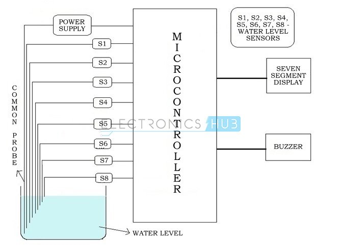
The Water Level Indicator employs a simple mechanism to detect and indicate the water level in an overhead tank or any other water container. The sensing is done by using a set of nine probes which are placed at nine different levels on the tank walls (with probe9 to probe1 placed in increasing order of height, common probe (i.e. a supply carrying probe) is placed at the base of the tank). The level 9 represents the “tank full” condition while level 1 represents the “tank empty” condition.
When the water-level is below the minimum detectable level (MDL), the seven segment displays is arranged to show the digit 1, indicating that the tank is empty, When the water reaches level1 (but is below level2) the connection between the probes gets completed (through the conducting medium – water) and the base voltage of transistor increases. This causes the base-emitter junction of transistor to get forward biased, this switches transistor from cut-off to conduction mode thus PIN (B0) of microcontroller is pulled to ground hence, the corresponding digit displayed by the seven segment display is 2. The similar mechanism applies to the detection of all the other levels. When the tank is full, all inputs to microcontroller become low and all its outputs go high. This causes the display shows a 9 also in this case a buzzer sound is given, thereby indicating a “tank full” condition.
Most water level indicators are equipped to indicate and detect only a single level. The Water Level Indicator implemented here can indicate up to nine such levels and the microcontroller displays the level number on a seven segment display. So, not only is the circuit capable of cautioning a person that the water tank has been filled up to a certain level, it also indicates that the water level has fallen below the minimum detectable level. This circuit is important in appliances such as the water cooler where there is a danger of motor-burnout when there is no water in the radiator used up also it can be used in fuel level indication.

Water Level Indicator Project Features:

  • Easy installation.
  • Low maintenance.
  • Compact elegant design.
  • The Automatic water level controller ensures no overflows or dry running of pump there by saves electricity and water.
  • Avoid seepage of roofs and walls due to overflowing tanks.
  • Fully automatic, saves man power.
  • Consume very little energy, ideal for continuous operation.
  • Automatic water level controller provides you the flexibility to decide for yourself the water levels for operations of pump set.
  • Shows clear indication of water levels in the overhead tank.

Hardware Description:

Water Level Indicator Project Block Diagram:

Water Level Indicator Block Diagram
Figure 2.1.1 Block diagram

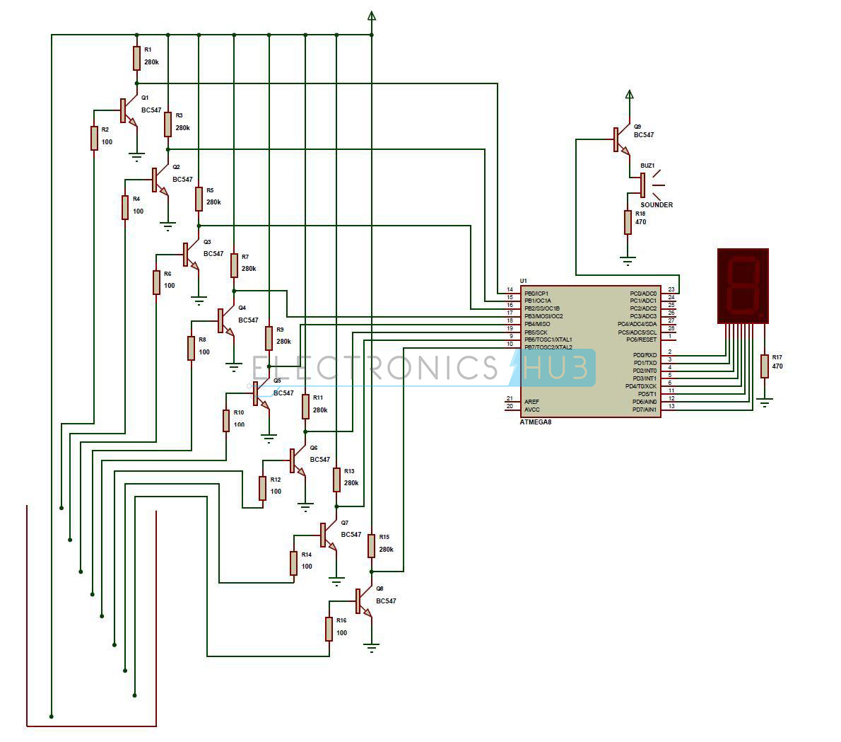
Water Level Indicator Project Circuit Diagram:

Water Level Indicator Schematic Diagram

Water Level Indicator Project Description:

This is the circuit diagram and description for water level indicator.
  • A constant 5v power supply is given to the microcontroller and rest of the circuit from a battery.
  • The tank has 9 conductive type sensors (other types of sensors have been mentioned earlier but in our project only conductive type are used) embedded into it and 8 wires of sensors out of 9 are connected to transistors and the 9th is connected to 5v+ supply.
  • The use of transistor is it acts as inverter (i.e. in on state gives low voltage at output and in non conducting state gives high voltage at its output), all transistors outputs are connected to 1,2,3,4,5,6,7,8 pins (PORTB) of microcontroller.
  • Seven segment display is connected to pin no. 33 to 40 (PORTA). It is connected in common cathode fashion.
    The Output for the 7th level is not only shown in seven segment display but also indicated with a discontinuous buzzer sound.
  • Output for the 8th level (i.e. tank full condition) is not only shown in seven segment display but also indicated with a continuous buzzer sound.

Operation:

The operation of this project is very simple and can be understood easily. In our project “water level indicator” there are 3 main conditions:
  1. There is no water available in the source tank.
  2. Intermediate level i.e. either of 3rd to 7th level.
  3. There is ample amount of water available in the source tank.
So let us discuss on the more about these 3 conditions

CONDITION 1: Water not available

When the tank is empty there is no conductive path between any of the 8 indicating probes and the common probe (which is connected to 5v+ supply) so the transistor base emitter region will not have sufficient biasing voltage hence it remains in cut off region and the output across its collector will be Vc approximately 4.2v. As in this case the microcontroller is used in the active low region (which means it considers 0-2 volts for HIGH and 3-5 volts for LOW) now the output of transistor which is 4.2v approximately will be considered as LOW by the microcontroller and hence the default value given by microcontroller to the seven segment display is 1 which indicates as the tank is empty.

CONDITION 2: Intermediate levels

Now as the water starts filling in the tank a conductive path is established between the sensing probes and the common probe and the corresponding transistors get sufficient biasing at their base, they starts conducting and now the outputs will be Vce (i.e. 1.2v-1.8v) approximately which is given to microcontroller. Here the microcontroller is programmed as a priority encoder which detects the highest priority input and displays corresponding water level in the seven segment display. In this project while the water level reaches the 7th level i.e. last but one level along with display in seven segment a discontinuous buzzer is activated which warns user that tank is going to be full soon.

CONDITION 3: Water full

When the tank becomes full, the top level probe gets the conductive path through water and the corresponding transistor gets into conduction whose output given to microcontroller with this input microcontroller not only displays the level in seven segment display but also activates the continuous buzzer by which user can understand that tank is full and can switch off the motor and save water.

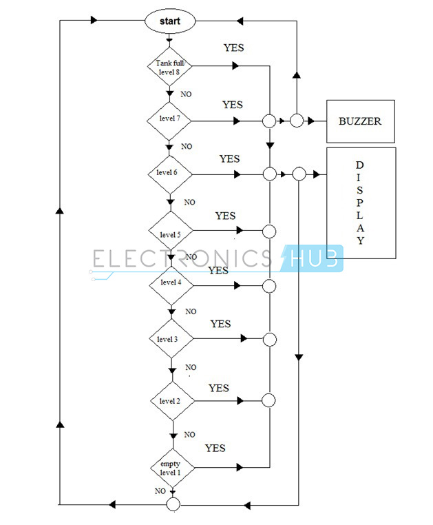
Flow Chart:

Water Level Indicator Flow ChartFigure 4.2.1 Flow chart
Flow chart gives the clear and easy understanding of the project. The process goes on as follows:
The microcontroller checks if the tank is full if the condition is satisfied it indicates the same on display unit and also sounds a buzzer if the condition fails it checks if the tank is filled upto level 7 and this process continues and the corresponding level is indicated in the display unit.

Conclusion and Scope:

Applications of Water Level Indicator:

  • Automatic Water level Controller can be used in Hotels, Factories, Homes Apartments, Commercial Complexes, Drainage, etc., It can be fixed for single phase motor, Single Phase Submersibles, Three Phase motors. (For 3Æ and Single Phase Submersible Starter is necessary) and open well, Bore well and Sump. We can control two motor and two sumps and two overhead tanks by single unit.
  • Automatic water level controller will automatically START the pump set as soon as the water level falls below the predetermined level (usually 1/2 tank) and shall SWITCH OFF the pump set as soon as tank is full.
  • Fuel level indicator in vehicles.
  • Liquid level indicator in the huge containers in the companies.

Automatic Plant Irrigation System

Automatic Plant Irrigation System

Here is a simple project more useful in watering plants automatically without any human interference. We may call it as Automatic plant irrigation system. We know that people do not pour the water on to the plants in their gardens when they go to vacation or often forget to water plants. As a result, there is a chance to get the plants damaged. This project is an excellent solution for such kind of problems.

Block Diagram of Automatic Plant Irrigation System:

Block Diagram of Electronic Plant Watering System
Explanation:
  • Circuit is not that much complicated. We use the basic concept in this circuit i.e. soil have high resistance when it is dry and has very low resistance when it is wet.
  • By using this concept we will make the system work. We insert two probes in the soil in such a way that that they will conduct when the soil is wet and they will not conduct when the soil is dry. So, when the probes do not conduct, system will automatically detect this condition with the help of HEX inverter which will become high when the input is low.
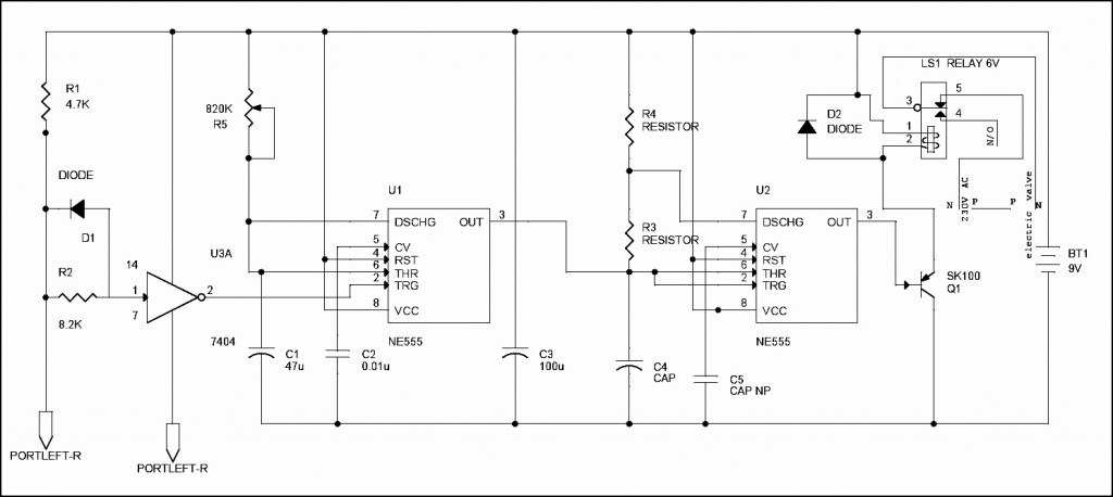
  • HEX inverter will trigger the NE555 Timer and this NE555 timer will trigger another NE555 which is connected to the output of first NE555. Now the second NE555 which is configured as astable multivibrator will help to switch on the Electric valve and as result, it will allow the water to flow to the soil.
  • When the water wet the soil, probes will again conduct and make the output of 7404 low which will make the first NE555 to low and also drive remaining circuit to low. So, automatically it will switch off the valve.
Main Components in Automatic Plant Irrigation System:
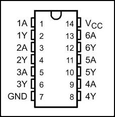
Hex Inverter 7404: the main function of the inverter is to give the complemented output for its input i.e. it will give output which is opposite to input. For example, if the input is low to the inverter, then the output will be high. Just like the normal inverter which gives high output when the input is low and gives low output when the input is high. 7404 IC will be having six independent inverters; Operating supply voltage is around 4.75V minimum to 5.5V maximum, normal supply voltage is 5V. They are used in different applications like inverting buffers, drivers, hex inverters etc. 7404 IC will be available in different packages like DIP (dual inline package), QFP (Quad Flat Package) etc. The pin configuration of Hex Inverter 7404 is shown below.
Inverter Pin Configuration

Circuit Diagram of Automatic Plant Irrigation System:

Circuit Diagram of Electronic Watering Plant System
Circuit Explanation:
  • We are all well aware that the plants will die due to lack of water in the soil. Soil will have high resistance when it is dry and it will have very low resistance when soil is wet. We use this simple logic to water the plants and make the circuit work.
  • Two probes which are connected to the circuit are placed into the soil. The two probes will conduct only when soil is wet (resistance is low) and they cannot conduct when soil is dry due to high resistance. The voltage is given to the probes to conduct is given from the battery connected to the circuit.
  • When the soil is dry it will produce large voltage drop due to high resistance. This is sensed by 7404 hex inverter and makes the first NE555 timer trigger which is configured as monostable multivibrator with the help of a electrical signal.
  • When the first NE555 is triggered at pin 2, it will generate the output at pin 3 which is given to the input of second NE555 timer. The second 555 timer is configured as astable multivibrator which got triggered by the first 555 timer and will generate the output and drive the relay which is connected to the electrically operated value through the transistor SK100. You can use a heat sink for SK100 transistor if it is dissipating more heat.
  • The output of second NE555 timer will switch on the transistor SK100 which will drive the relay. Relay which is connected to the input of electrical value and output of value is given to the plant plots through the pipe.
  • When transistor has turned on relay, it will open the valve and water is poured on to the plants pot. When the water content in the soil is increased, the resistance in the soil will get decreased and conduction of the probes will get started which will make the 7404 Inverter to stop the triggering of first 555 timer. Ultimately it will stop the electrical valve which is connected to the relay. Variable resistor (R5) and capacitor (C1) are used to adjust the valve when to we want to conduct the probes.
  • The capacitor C5 (0.01uf) is used to ground, the CV pin of second NE555 timer. C3 will remove the AC noise and allow only DC to the remaining circuit. C4 and R3 will constitute to configure the NE555 in astable multivibrator.
Values of the Components in the Circuit:
  • Capacitor (C4) = 10u 16V.
  • Capacitor (C5) = 0.01u.
  • Resistor (R3) = 27K
  • Resistor (R4) = 27K
  • Diode (D1 and D2) = IN4148
  • Relay = 6V, 150 ohms

Motor speed monitors and control system using GSM modem

Motor speed monitors and control system using GSM modem

              The purpose of  this project   is  to control   the speed and direction of  DC Motor  using Microcontroller and GSM Modem with password protection.    This uses a PWM  Pulse Width Modulation) technique to control the speed of motor from 0% to 100%. The   speed   of   the  motor   is  measured   using   contact-less   speed  measurement technique.  Speed control is done using PWM (Pulse Width Modulation) method.    User can  send SMS messages   to  control   the  motor   speed  and direction. A GSM modem attached to the control unit handles automatic SMS sending and receiving process.   As this monitoring and controlling can be done by any mobile phone, we provided a security feature by implementing password-based protection. User has to send the password along with the commands to be controlled.
           GSM Modem connected to microcontroller unit is used to control the motor and know the motor live speed. Microcontroller automatically reads the SMS messages stored in the SIM card and takes necessary action like speed control, direction control etc. There will be a particular code that needs to be sent through SMS to set the speed and get the speed from the DC motor  


Features of this project:
1. Remote monitoring and controlling of DC motor.
2. Can be operated from anywhere in the world.
3. Reliable for industrial and domestic needs.
4. Automatic remote speed measurement.


Hall Effect Sensor based non-contact tachometer for electrical motors speed measurement

Hall Effect Sensor based non-contact tachometer for electrical motors speed measurement

       The purpose of this project is to design and construct a non-contact type of Tachometer. A tachometer(also called a revolution-counter, rev-counter, or RPM gauge) is an instrument that measures the rotation speed of a shaft or disk, as in a motor or other machine. Hall Effect sensors typically use a rotating target attached to a wheel, gearbox or motor. This target may contain magnets, or it may be a toothed wheel. The teeth on the wheel vary the flux density of a magnet inside the sensor head.

        This project consists of a Hall effect sensor connected to a microcontroller unit. The sensor signals from Hall effect sensor are sent to microcontroller for rpm measurement. These measured final values arc displayed on a LCD display connected to microcontroller.

Engineering Project Topics and Project Ideas

Single Phasing Monitoring and Prevention System for 3-phase Industrial Loads


The aim of this project is to construct a single phasing monitor and prevention system using 8-bit microcontroller. Anti-single phasing relays or single phasing preventer are required for critical loads and circuits. These are required because the normal overload protection doesn't trip on time. For large air-conditioning compressors, irrigation pumps these are sometimes, included.
      The purpose of this project is to develop an intelligent system that continuously monitors all the three phase voltages (High voltage AC) and if any of these three phases is disconnected then this system takes the preventive action. The preventive action could be disconnecting the power supply immediately to the load by operating an electromagnetic relay. This system also alerts the user using visual or audible indicators.

        This system consists of three optically isolated high voltage sensors for sensing the presence of high voltage in the respective circuits. One of the voltage sensors is connected to phase line of the supply and the other is connected to neutral line. A micro controller based control system continuously monitors the voltage in all the three phases of the power supply circuit. In ideal conditions all the three phases gets the same voltage. The visual indicators display the health status of all three phases (Red, Yellow and Green). But, when any of the phases gets disconnected then in such situations the micro controller-based system alerts the user about this in the form of visual or audible alerts.

Electrical Engineering Projects

  1. Mobile technology (GSM) based remote monitoring and control of digital Energy meter. Useful for Electricity Department personal for remote meter reading. Also useful to disconnect the power supply to consumer in case of non-payment of electric bill. This is also used to exchange messages like power cut timings with the consumers.
  2. Controlling AC lamp Dimmer through Mobile Phone (IEEE-2010).
  3. Multiple Transformers oil temperature monitoring with automatic circuit breaker operation with SMS based alerts.
  4. A Novel Wireless Self-powered Microcontroller-based Monitoring Circuit for Photovoltaic Panels in Grid-connected Systems (IEEE-2010).
  5. Wireless Energy Meter reading on hand-help device based on RF Transceiver.
  6. SCADA implementation based on wireless RF technology. (IEEE-2009).
  7. Method of Measuring Power Quality and Development of Monitor Device (IEEE-2010).
  8. Motor speed monitoring and control system using GSM modem.
  9. A Smart Card Based Prepaid Electricity System.
  10. High voltage fuse blown indicator with Voice based announcement system.
  11. Voice enabled devices switching for visually impaired.
  12. Industrial/power grid electrical parameter Data Acquisition system through wireless technology.
  13. DC Motors speed synchronization for rolling mills.
  14. Touch Screen based digital devices control system. This project is to build a Graphical LCD Touch Screen interface for switching electrical devices. The controlled devices can be of high voltage or low voltage.
  15. Construction of central control unit for Irrigation water pumps.  Cost effective method to control entire villagers water pumps with user level authentication. Illiterates friendly system.
  16. Wireless Energy Meter monitoring system with automatic tariff calculation.
  17. Home Network Configuring Scheme for All Electric Appliances Using ZigBee-based Integrated Remote Controller.
  18. Resistive Touch screen controlled contact less speed monitoring and controlling of dc motor with speed limit alerts.
  19. DC Motor Speed and direction control over GSM Mobile/Modem.
  20. Smart Wireless Temperature Data Logger (IEEE-2007)
  21. Energy meter monitoring and control system using SMS technology(IEEE-2007).
  22. Energy meter data logging system with Realtime clock and KWH readings. Very useful for historical data logging and analysis.
  23. Energy meter per-day average, Max and Min Load display on Graphical LCD.
  24. MMC/SD card based data logger for energy meter with time and KWH readings for historical data logging and analysis.
  25. PIR based energy conservation system for corporate Computers and lighting system.
  26. Development of Zigbee based Street Light (IEEE-2008)
  27. Wireless power theft monitoring system and indication at local substations.
  28. Touchscreen controlled lamp dimmer for next generation apartments.
  29. Wireless electrical devices monitoring and controlling system for industrial applications.
  30. Microconroller and Touchscreen controlled motor speed and direction controlling system.
  31. Touchscreen operated industrial oil dispensing system (OIL SCADA).
  32. An On-line Monitoring System of Temperature of Conductors and Fittings Based on GSM SMS and Zigbee(IEEE-2008).
  33. 4-wired resistive touch screen controlled lamp dimmer for next generation apartments with Optical isolation and zero crossing detectors. 
  34. Dual (active and standby) Lithium-ion battery charger for continuous non-interrupted power supply to critical loads.
  35. Graphical LCD and Touch Screen based Electrical devices control system.
  36. Implementation of wireless sensors network based industrial temperature monitoring system.
  37. Touchscreen based advanced temperature monitoring and control system with graphical LCD.
  38. GSM based Irrigation Water Pump Controller for Illiterates (No Mobile phone operation knowledge required).
  39. Triac and optically isolated diac based electrical oven temperature monitoring and controlling system with zero-crossing detector.
  40. High power LED based intelligent streetlight controlling system with automatic brightness control with vehicle presence sensor (GSM optional).
  41. Timer based Electrical Oven temperature monitoring and control for Metal Industries.
  42. GSM based SCADA implementation using Microcontroller.
  43. 3-phase irrigation water pump controller for illiterates using dual GSM Modems.
  44. Microcontroller based Substation Monitoring and control.
  45. Microcontroller based Generator/Alternator Control and Monitoring System
  46. Electrical Data (voltage, current, frequency etc...) Logger. The purpose of this project is to log electrical data at remote locations like substations. The data is sensed using various electrical sensors and processed by microcontroller. This processed data is stored in a MMC memory stick connected to the microcontroller board. This data can be downloaded to computer for further processing.
  47. Hall Effect sensor based non-contact Tachometer for electrical motors speed measurement.
  48. Microcontroller based Single phasing preventor.
  49. IR Remote controlled Irrigation water pump controller with single phasing protection.
  50. Microcontroller based Solar Tracker with Stepper Motor Control.
  51. Auto-Credit Energy Metering System using mifare card.
  52. PWM based DC Motor Closed loop Speed Controller.
  53. RS485 based SCADA system for longer distance powered devices
  54. Radio Frequency (RF) based Wireless Control Of DC/Stepper Motor Speed Control.
  55. RF based Wireless Electrical Devices Controller.
  56. Motor Speed Monitoring over GSM Mobile.
  57. Microcontroller based refrigeration control system.
  58. Timer based automatic power cutoff for industrial sealing/packaging machines.
  59. Wireless SCADA.
  60. GSM/Mobile/Cell Phone Based Device Monitoring and Control.
  61. GSM Based Automatic Irrigation Water Controller System
  62. Automatic Intelligent Plant Watering System
  63. IR (Infrared) Remote based Stepper Motor Speed and Direction Controller
  64. RC5 IR Based Remote Device Switching
  65. The Robot that follows the (Infrared) Light
  66. Frequency Locked Loop DC Motor speed monitoring and control system.
  67. Digital Tachometer (Non-contact)
  68. Digital Voltage, Current and Frequency Meter.
  69. SCADA system design and construction for real-time electrical parameter monitoring and control.
  70. Transformer oil temperature monitoring with automatic Circuit Breaker operation.
  71. GSM/Mobile/Cell Phone Based Device Monitoring and Control System.
  72. Energy Tapping Identifier Through Wireless Data Acquisition System.
  73. Substation Fuse blown Indicator.
  74. Mobile phone controlled Street Light monitoring and control system.
  75. UPS battery monitoring system over GSM for high availability systems (banking/finance/medical etc).
  76. DTMF mobile phone controlled dam water gates controlling system with high-level protection.
  77. DC Motor Speed and direction control using RF/IR/Zigbee technologies.
  78. Hazardous chemical valve control system with stepper motor and line of site remote control.
  79. Contact less Motor speed monitoring on Graphical display with high and low speed alerts.
  80. Design and construction of Earth fault relay for single phase power system.
  81. RF transceiver (Zigbee/X-Bee) based energy meter monitoring system. (Energy Meter reading on PC over wireless comm.)
  82. Talking energy (KWH) meter.
  83. Sine wave Inverter.
  84. Transformerless Variable Frequency Drive
  85. Solar operated Liquid Vending machine
  86. DC-DC Converter
  87. Green wind energy for rural electrification
  88. AC-AC Converter
  89. Earth Fault relay for 3-phase power system
  90. Programmable current relay for high speed protection.
  91. MPPT Optimal Power Point Tracking system for Solar PV panels.
  92. Password enabled pre-paid liquid/milk dispensing system.
  93. High voltage fuse blown indicator with display on PC with optical isolation between PC and HV bus bars
  94. Solar based air compressor pump for car bike tire inflate
  95. Voice operated Intelligent Fire extinguisher vehicle
  96. An On-line Monitoring System of Transmission Line Conductor De-icing(IEEE-2008).
    Designing of Haptic Keypad with Magnetic Door Lock system